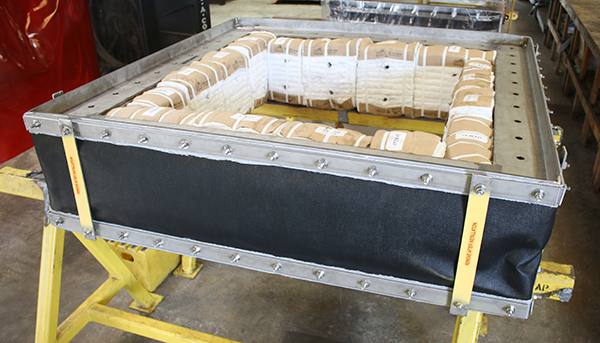
When a major energy provider needed to replace a critical elbow pressure balanced expansion joint at one of its Nevada power generation facilities, it turned to a trusted manufacturer.
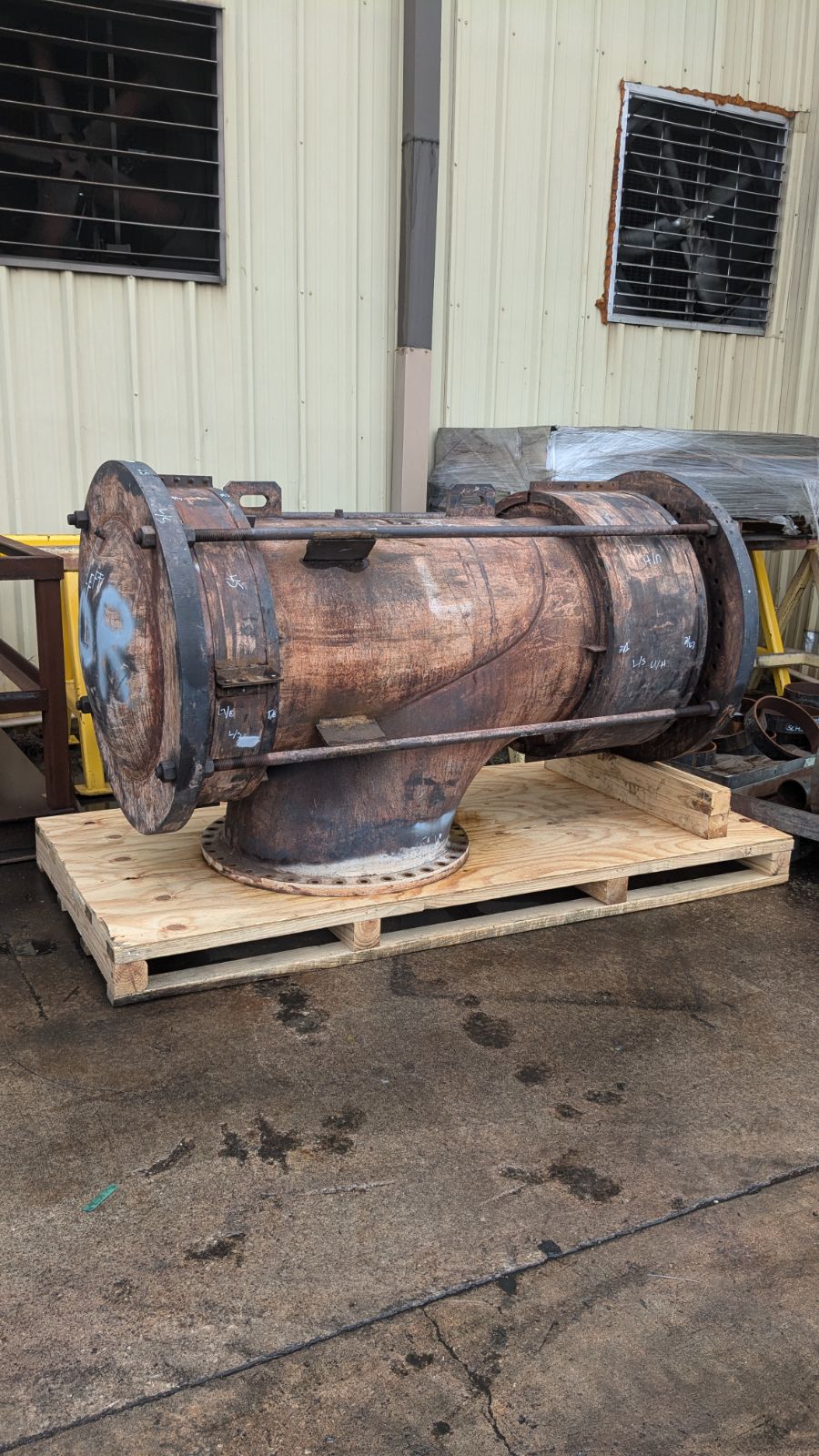
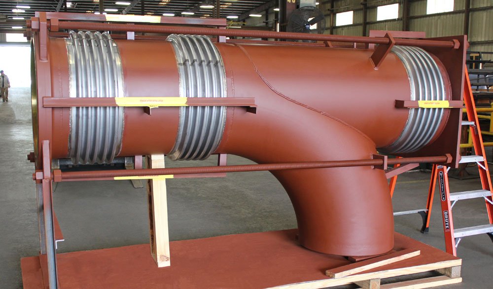
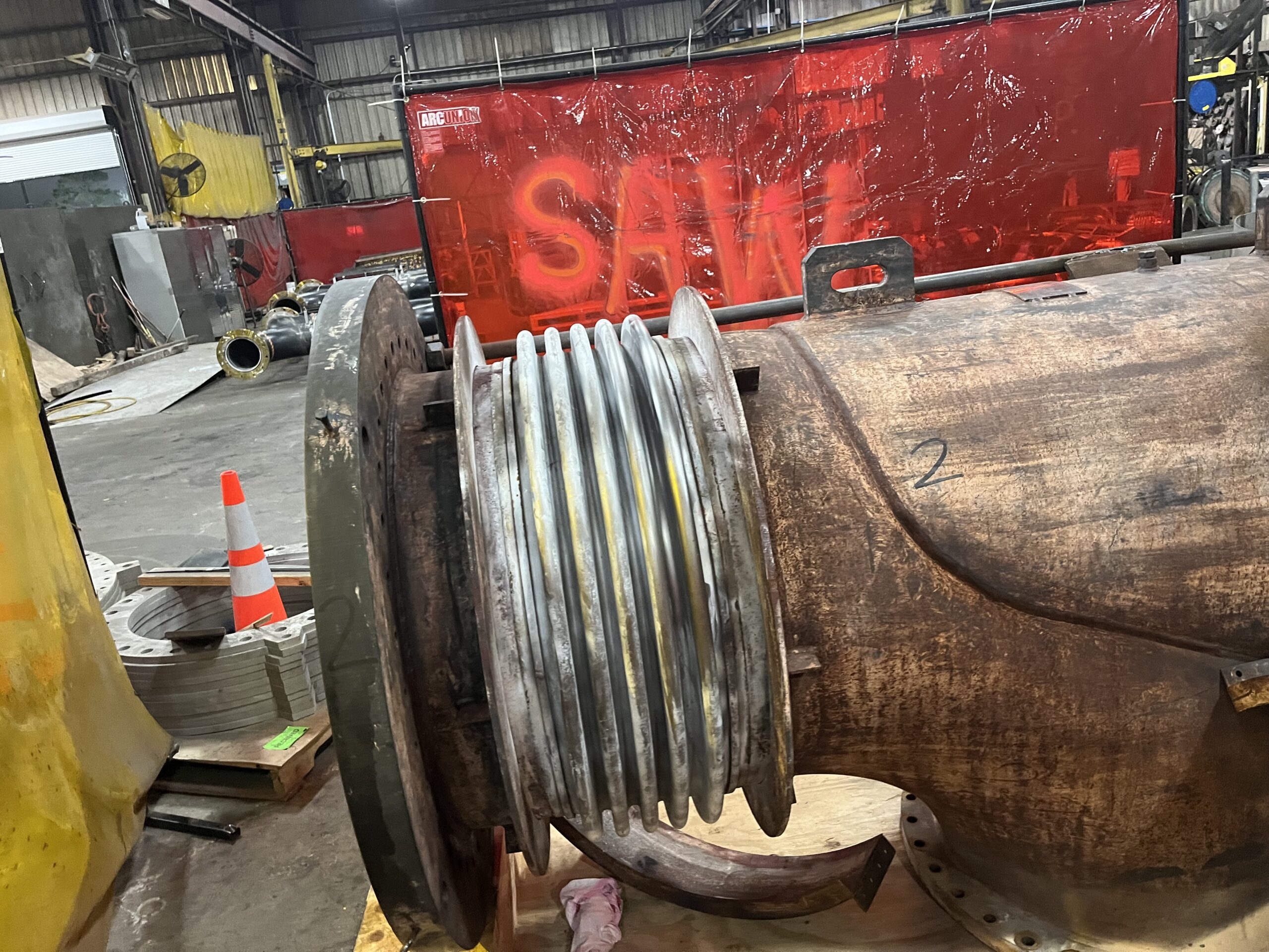
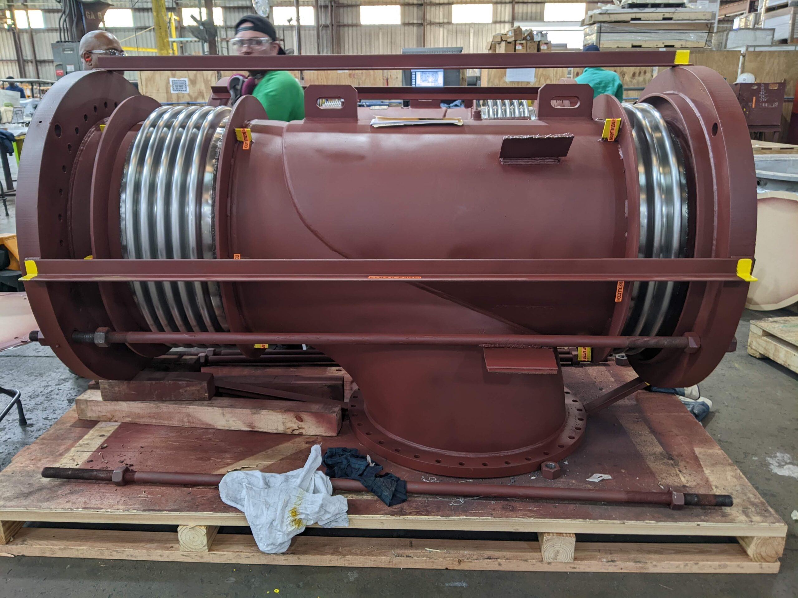
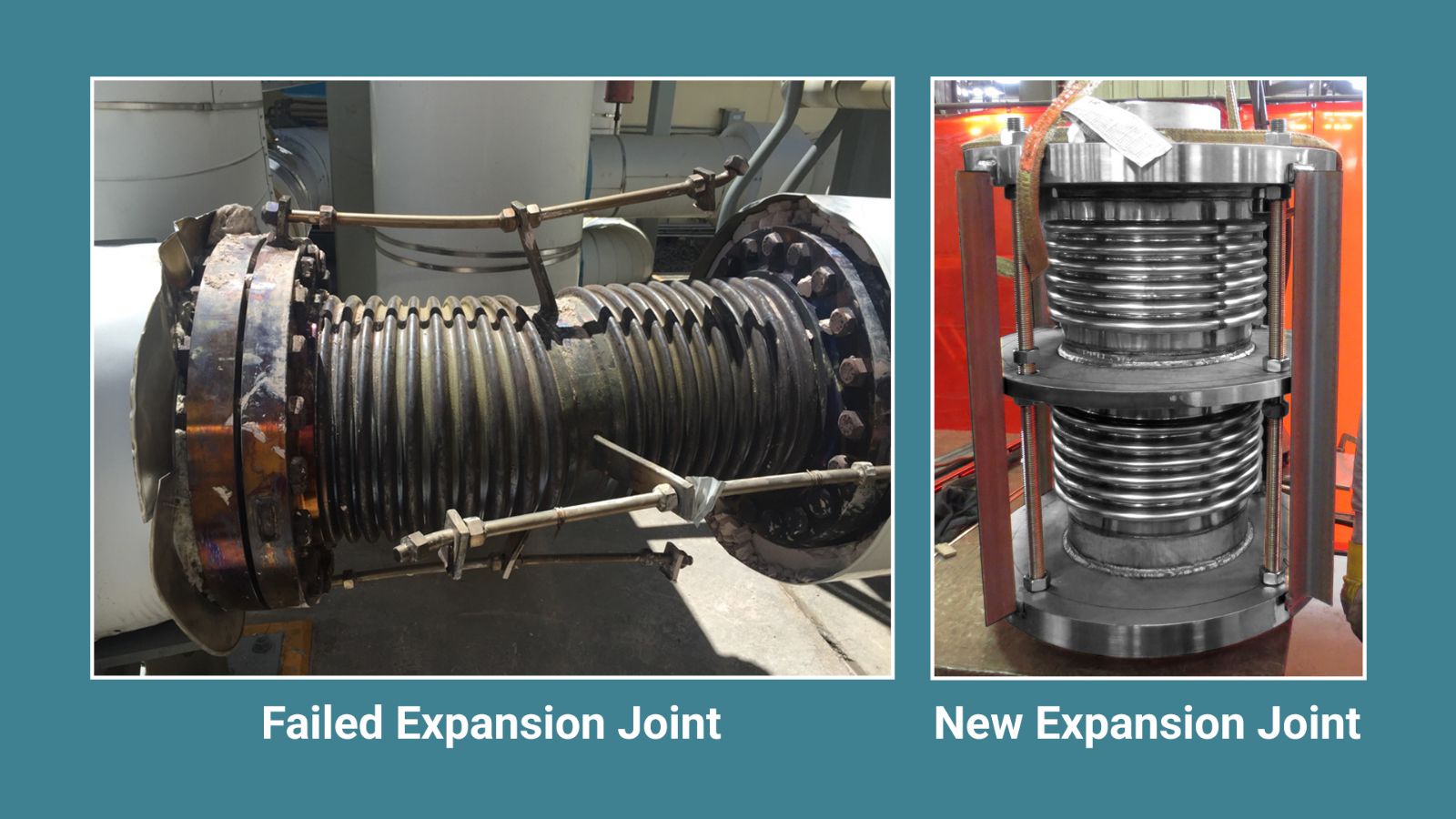
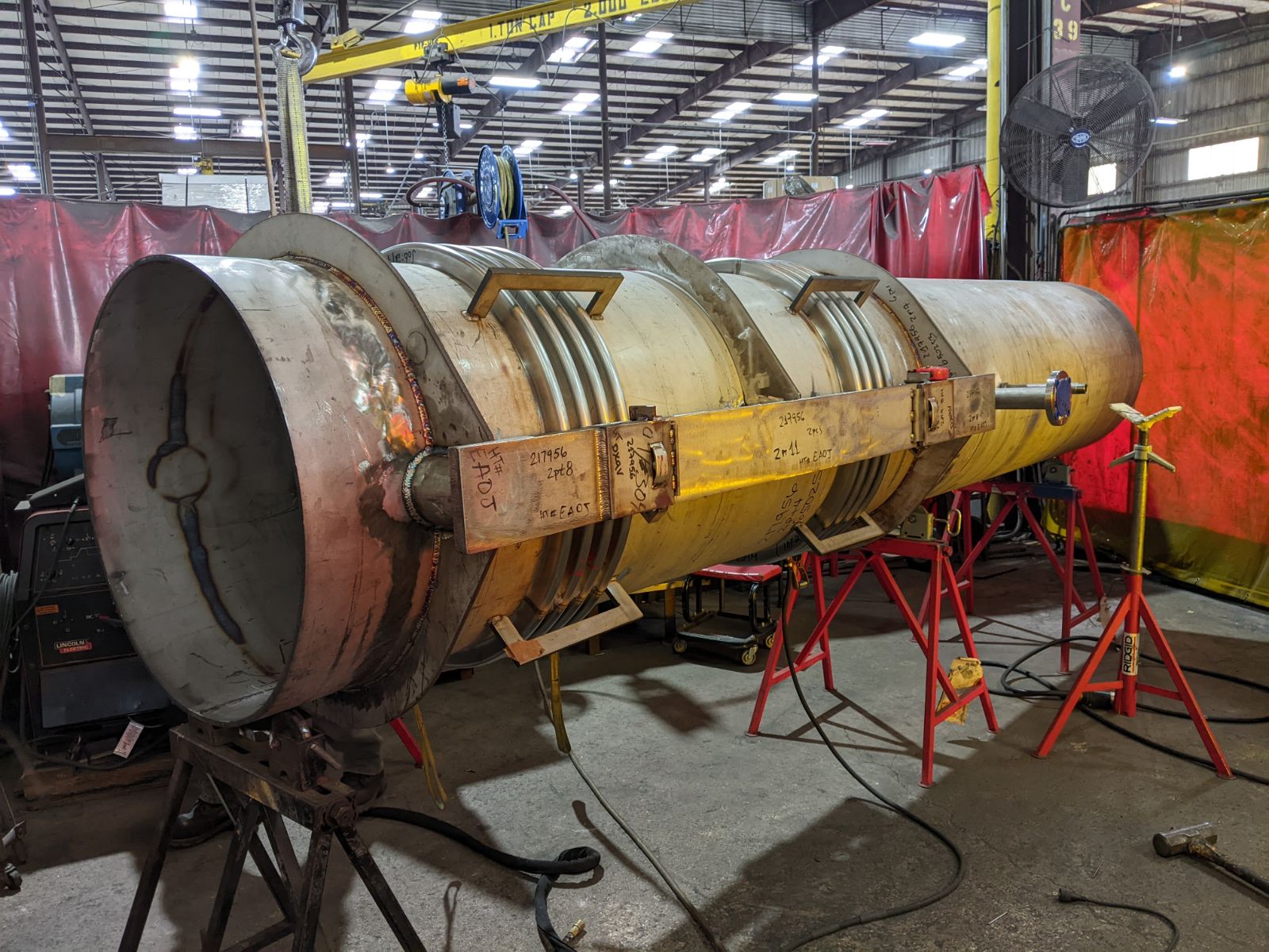
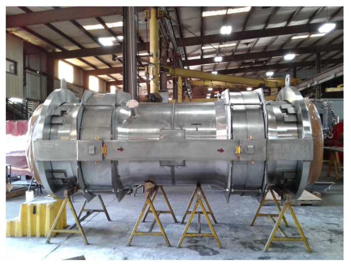
US Bellows re-engineered and refurbished this elbow-pressure balanced expansion joint, which had lasted more than 25 years. The original unit, manufactured in 1975, is for a GE steam turbine used in the cross-over pipe section to manage thermal expansion while minimizing loads on the turbine. US Bellows refurbished and replaced the bellows 25 years ago. After the bellows has a full-service life the client turned to us for another replacement—and we turned it around in three weeks.
The Challenge The expansion joint required custom fabrication to exact specifications, with a three-week deadline to minimize downtime at an active gas-fired power plant.
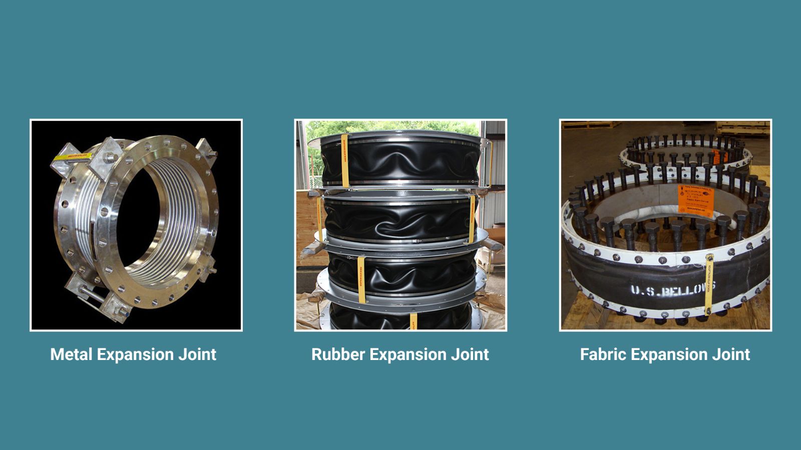
The US Bellows Difference Expansion joints are a technically demanding, artisanal product line requiring rare skills, thin-gauge superalloy welding, and custom machinery. Here’s what made it possible:
- Scale & Capacity: US Bellows shipped nearly 4,500 expansion joints last year, backed by a 15% shop expansion and new equipment including a CNC plasma table, bellows shear, Davi roller, additional in-house designed punch equipment, clean-room operations, and additional cranes.
- Workforce Flexibility: Our expansion joint team can draw on 40+ additional trained welders and 30+ cut shop and layout personnel when needed — ensuring we can surge capacity to meet urgent deadlines. Our ability to be vertically integrated with our other divisions from a manufacturing standpoint gives us the optimal set up for fastest time to market in these scenarios.
- Engineering Expertise: Two dedicated industrial engineers with master’s degrees drive on-floor scheduling and process efficiency, with the entire production process mapped for rapid response.
- Digital Work Instructions: Deployed across all key production steps, enabling precision, consistency, and fast execution — even on complex custom fabrications.
- Enhanced Quality Control: Detailed drawing review checklists before fabrication reduce revisions and reworks, so we get it right the first time.
As an EJMA-certified manufacturer, all of our expansion joints are designed and fabricated in accordance with EJMA standards and ASME B31.1 Power Piping Code for power applications — ensuring every unit meets the rigorous demands of power generation environments.
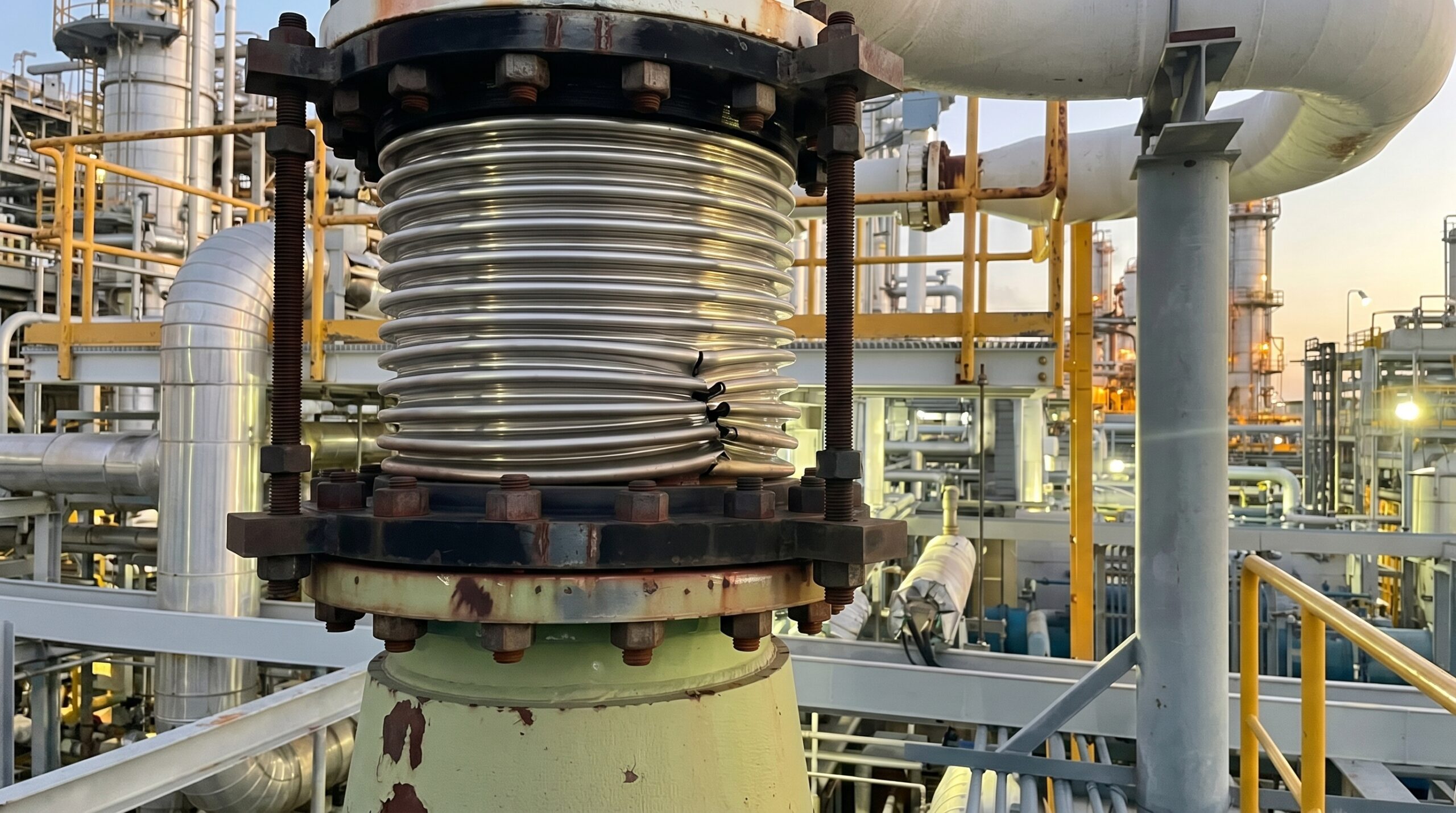
Why the Elbow Pressure Balanced Expansion Joint Matters
In today’s power landscape — driven by AI data centers, industrial electrification, and aging grids — turbines must operate with near-zero downtime. Even a few millimeters of unintended movement from thermal expansion in steam lines can cause casing distortion, rotor misalignment, and bearing failure.
The Elbow Pressure Balanced Expansion Joint (EPBEJ) is engineered to prevent exactly that — while solving a challenge the inline design cannot: changes in piping direction.
- Force Neutralization at the Elbow: A balancing bellows positioned after the elbow cancels out pressure thrust in both the axial and lateral directions via tie rods — so the turbine flange experiences zero pressure-related loads, even through a 90° turn.
- Zero-Anchor Load: The turbine only “feels” the minimal spring rate of the bellows — negligible compared to the thousands of pounds of thrust generated by pressure acting on directional changes in high-pressure steam lines.
- Direction Change Without Penalty: The elbow design absorbs thermal growth across a piping bend, eliminating the need for separate directional expansion joints or complex guided pipe loops at header-to-turbine connections.
- Reduced Civil Costs: The self-balancing design eliminates the need for massive concrete thrust anchors at elbow locations — historically among the most heavily loaded anchor points in a turbine hall.
- Compact Routing in Tight Layouts: Where piping must turn to reach a turbine nozzle, the EPBEJ replaces what would otherwise require multiple components — an elbow, two expansion joints, and intermediate anchoring — with a single, integrated assembly.
- Reliability in Cycling: As peaking plants ramp up and down daily to balance renewables, the EPBEJ absorbs constant expansion and contraction cycles at directional transitions that would otherwise fatigue turbine nozzle connections and elbow welds alike.
A Legacy of Quality The original elbow pressure balanced expansion joint served this client for 50+ years. When the time came for a replacement, they came back to us. That’s the US Bellows standard — products built to last, and a team built to deliver.
60% of our work at US Bellows is replacement units for operating facilities all over the world. We are not always the OEM — but we are always the manufacturer that delivers.
At US Bellows, we build lasting partnerships with the power industry — one precision-engineered solution at a time.
Read More


 In a complex piping system, the smallest component often carries the heaviest burden. A
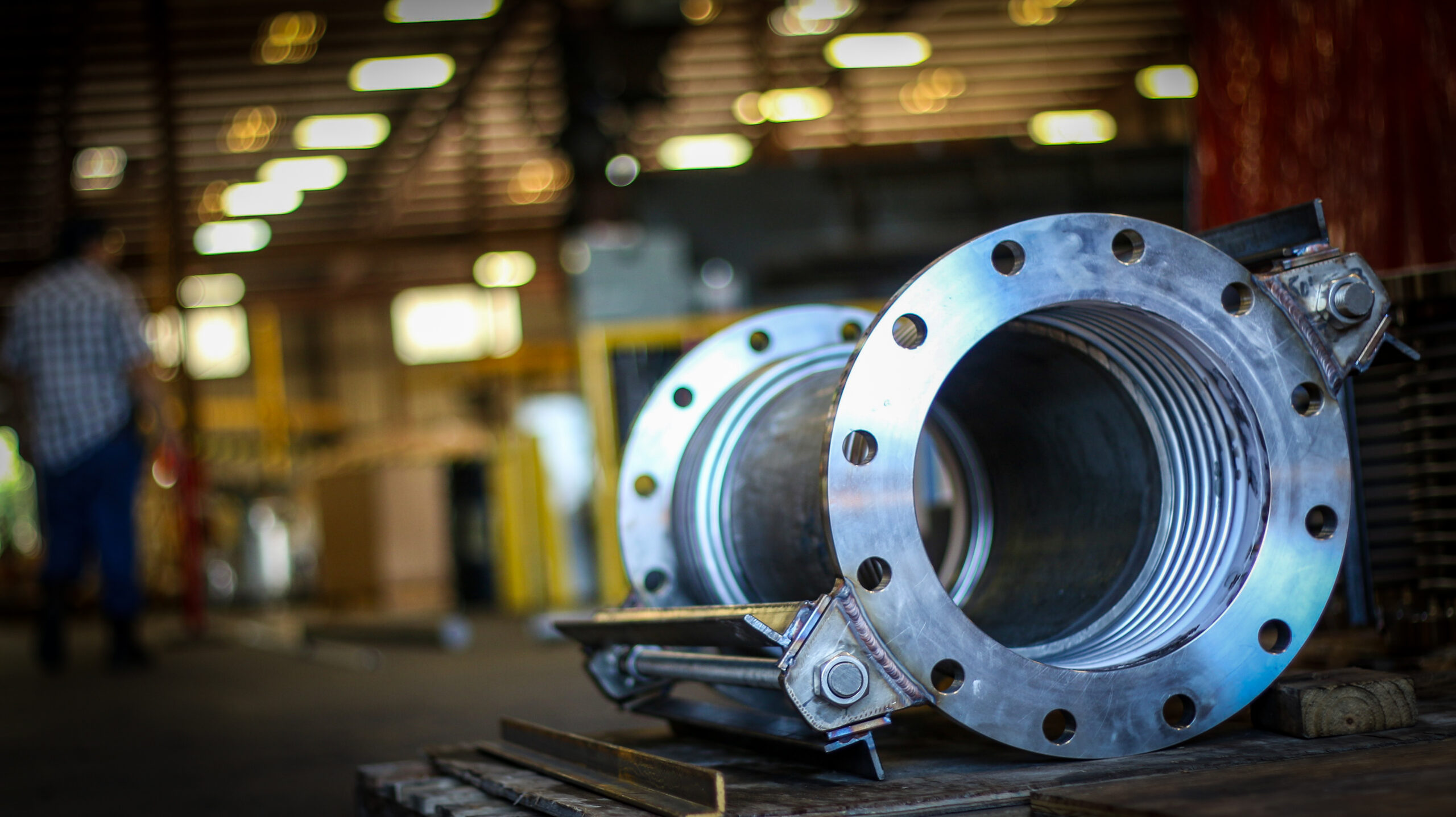
 Metal flanges are a cornerstone of modern industrial piping systems, but their role extends beyond just connecting pipes. They are an essential, pressure-resistant component of expansion joints, which manage thermal movement and stress in piping systems. Industrial piping designers need to understand and focus on the cooperative relationship between
 While
While