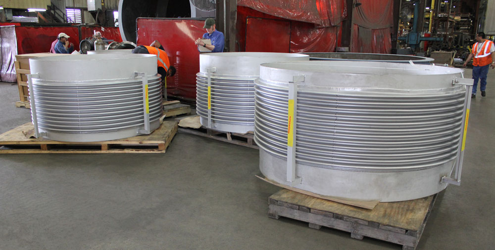
Overview
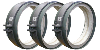
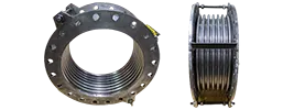
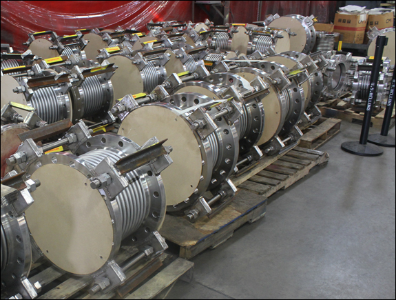
A standard piping expansion joint absorbs axial compression and extension along a single straight pipe run. When engineers calculate anticipated pipe expansion, they often select a unit featuring durable stainless steel bellows to handle extreme temperatures and corrosive fluids.
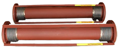
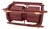
This specific pipe bellows design protects adjacent equipment from mechanical stress due to the pipe growth. For steam applications, a dedicated steam expansion joint provides necessary pressure containment and structural stability in the system.
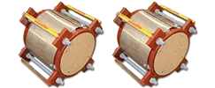
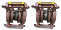
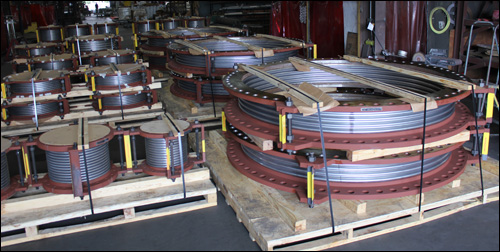
Managing overall pipework expansion sometimes requires more lateral flexibility than a single unit can provide. In those specific situations, professionals might specify a universal expansion joint instead. However, for straightforward axial movement, a single assembly remains the most reliable solution.
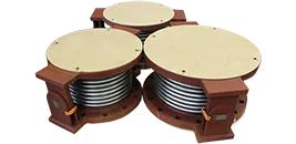
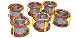
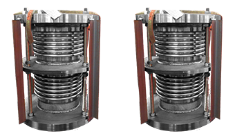
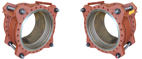
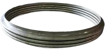
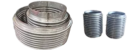
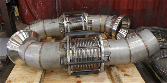
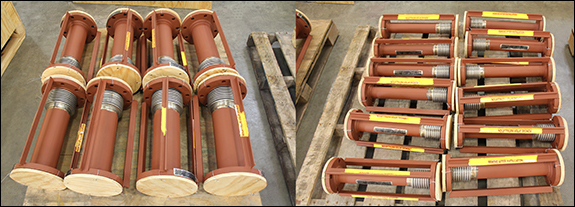
Single and Multi-ply Expansion Joint Bellows
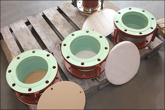
Single Expansion Joints by Nominal Diameter
3 1/2 Inch Single Expansion Joint
4 Inch Single Expansion Joint
5 Inch Single Expansion Joint
6 Inch Single Expansion Joint
8 Inch Single Expansion Joint
10 Inch Single Expansion Joint
12 Inch Single Expansion Joint
14 Inch Single Expansion Joint
16 Inch Single Expansion Joint
18 Inch Single Expansion Joint
20 Inch Single Expansion Joint
22 Inch Single Expansion Joint
24 Inch Single Expansion Joint
26 Inch Single Expansion Joint
28 Inch Single Expansion Joint
30 Inch Single Expansion Joint
32 Inch Single Expansion Joint
34 Inch Single Expansion Joint
36 Inch Single Expansion Joint
38 Inch Single Expansion Joint
40 Inch Single Expansion Joint
42 Inch Single Expansion Joint
44 Inch Single Expansion Joint
46 Inch Single Expansion Joint
48 Inch Single Expansion Joint
50, 52, 54 Inch Single Expansion Joint
60, 66, 72 Inch Single Expansion Joint
84, 96 Inch Single Expansion Joint
108, 120, 132 Inch Single Expansion Joint
144, 156 Inch Single Expansion Joint
Features
- Absorbs small amounts of axial, lateral, and angular movements
- Deflect in any direction
- Most economical
- Must be guided
- Requires main and directional anchors
Technical Information
Installation & Maintenance (Metallic Expansion Joints)
Metal Bellows Material
Types of Metallic Bellows Deflections
Bellows Expansion Joint Loads
How to Look for Signs of Expansion Joint Failure
View more Technical Information
FAQs
Q: What is the primary function of a piping expansion joint in a single configuration?
A: A single assembly is designed to absorb axial pipe expansion along a straight section of the system.
Q: How does a single unit compare to a universal expansion joint?
A: While a single unit primarily handles straight-line movement, a universal expansion joint is specifically engineered to accommodate large amounts of lateral offset during pipework expansion.
Q: What materials are used to manufacture a durable pipe bellows?
A: Engineers typically specify a stainless steel bellows to ensure the component can safely withstand high pressures and resist corrosive process fluids. Nickel alloys are also specified for extreme environments and temperatures.
Q: Can a standard single assembly be used as a steam expansion joint?
A: Yes. When properly rated for extreme temperatures and high pressures, a single unit functions effectively as a steam expansion joint. This ensures the system manages thermal growth safely.
Q: Why is guiding important when managing pipe expansion with a single joint?
A: Proper alignment prevents the pipe bellows from buckling under pressure. Without strict structural guiding and spacing, the piping expansion joint may experience dangerous squirm and mechanical failure.
Other FAQS:
How do you do a fatigue life cycle test for bellows?
How long is a burst test on an expansion joint?
Case Studies
5/13/19: Single Expansion Joints Designed for an Oklahoma Pipeline
10/30/17: Single Expansion Joints for a Pipeline in Louisiana
5/30/15: 6″ Dia. Single Expansion Joint Designed for a Pipeline in Texas
3/17/14: Single Expansion Joints Manufactured for a Lab at Michigan State University
Request a Quote