Overview
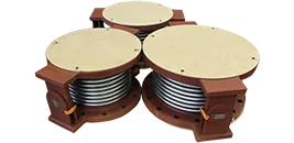
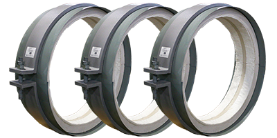
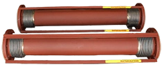
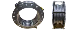
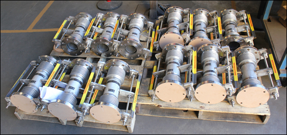
By using flanged expansion bellows, facilities can safely absorb axial and lateral movements. For systems requiring large lateral offsets, a universal expansion joint is often the preferred solution. These components ensure the system operates safely under pressure. They effectively protect sensitive equipment from mechanical stress.
A flanged expansion joint provides a secure connection to existing piping infrastructure. This design allows for easy installation and removal during routine maintenance. Piping engineers frequently specify HVAC expansion joints to accommodate thermal growth in cooling and heating systems.
Data Tables
5, 6, 8 Inch Universal Expansion Joints
10, 12, 14 inch Universal Expansion Joints
16, 18, 20 Inch Universal Expansion Joints
22, 24, 26 Inch Universal Expansion Joints
28, 30, 32 Inch Universal Expansion Joints
34, 36, 38 Inch Universal Expansion Joints
40, 42 Inch Universal Expansion Joints
44, 46, 48 Inch Universal Expansion Joints
50 Through 72 Inch Universal Expansion Joints
84 Through 144 Inch Universal Expansion Joints
Technical Information
Installation & Maintenance (Metallic Expansion Joints)
Metal Bellows Material
Types of Metallic Bellows Deflections
Bellows Expansion Joint Loads
How to Look for Signs of Expansion Joint Failure
View more Technical Information
FAQs
Q: What types of movement is a universal expansion joint designed to absorb?
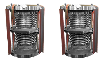
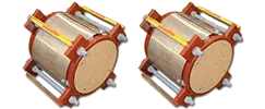
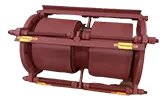
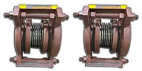
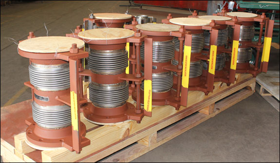
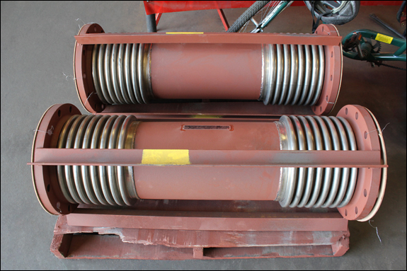
A: A universal expansion joint is primarily designed to absorb large amounts of lateral deflection in one or multiple planes. Because it consists of two separate bellows separated by a center pipe spool, and depending on the tie-rod configuration, it can also accommodate angular rotation, and in the case of limit or control rods, it can allow for axial movement.
Q: How does the length of the center spool affect the joint’s lateral movement capacity?
A: The center pipe spool connects the two individual bellows within the assembly. Increasing the length of this center spool increases the joint’s capacity to absorb lateral offset and allows the system to handle greater structural displacement without overstressing the corrugations.
Other Frequently Asked Questions:
Why do the universal expansion joints need to be tied?
Where should I use a universal expansion joint in piping?
How long should a universal expansion joint be?
How do you decide on the number of tie-rods in a universal expansion joint?
Case Studies
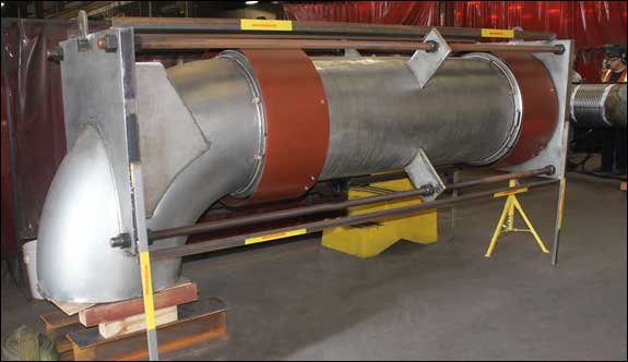
11/22/21: Universal Elbow Expansion Joints for Glycol Heat Transfer Piping
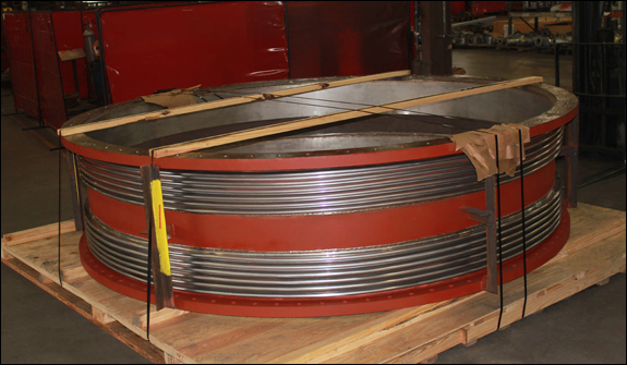
11/2/14: 60″ Dia. Universal Expansion Joint Designed for a Chemical Company
2/11/09: 20″ Tied Universal Expansion Joint
8/16/06: Tied Universal Expansion Joints for an Engineering and Construction Company
Request A Quote