Please read entire document prior to beginning Expansion Joint Installation. The recommendations in this document are to be used as a guide. Please use these instructions in conjunction with the approved drawing provided by U.S. Bellows. The approved drawing should be considered the governing document.
Receiving and Storage
Follow U.S. Bellows’ Receiving and Storage Instructions
2. Pre-Installation Checks
- Confirm dimensional data per U.S. Bellows’ approved drawing.
- Confirm duct/duct flanges are in good condition.
- Confirm duct/duct flanges are lined up correctly (ensure that lateral displacement and angular movement do not exceed agreed specifications).
- Prior to installing the expansion joint frames, the opening into which the expansion joint will be installed must be inspected to verify that the openings is in accordance with design tolerances. The expansion joint is not designed to accommodate installation misalignment, unless clearly specified as a design requirement.
- Make available the following tools/equipment to simplify the installation:
- Suitable/safe scaffolding
- Lifting equipment (fork lift, crane, hoist)
- Drill
- Come along
- Rope
- Pry Bar
3. Expansion Joint Installation
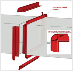
- Using the U.S. Bellows drawing, organize the parts per drawing information and “match markings” on parts.
- Clean duct/flange surfaces and prepare for welding.
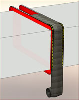
- Tack weld frame segments into place. If the expansion joint has a liner, make certain that the flow arrow of the expansion joint/liner is in the proper system flow direction. If liner ships loose, install frames first to allow seal weld access.
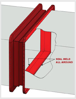
- Seal weld frames.
- Install accumulation barrier/insulation pillow — if required.
4. Accumulation barriers or Insulation Pillows — IF REQUIRED
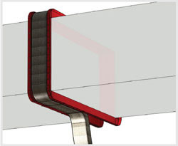
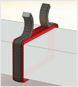
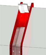
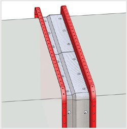
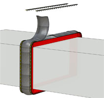
Accumulation Barriers are typically designed to fill the entire cavity of the expansion joint. Wrap the accumulation barrier around the duct/expansion joint. Pack the accumulation barrier into the cavity of the expansion joint. The liner will prevent the barrier from falling into the duct. Use thread or wire to tie across the breach opening to support accumulation barrier during installation. Remove thread or wire prior to installing the fabric belt element.
 |
 |
While splicing or joining the ends of the barrier, “stagger” the overlaps of the materials to prevent thickness build-up.
 |
 |
5. Accumulation barriers or Insulation Pillows — IF REQUIRED
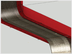
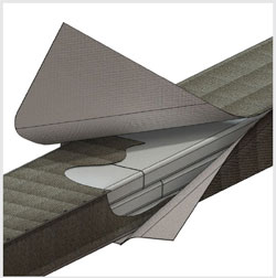
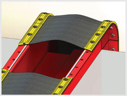
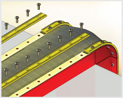
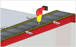
Insulation pillows are typically designed to prevent high temperatures from contacting the fabric belt material; therefore it is critical to attach the pillow in place. There are multiple ways to attach the pillow. Follow U.S. Bellows drawing for details. Pinning the pillow to the liner (as shown) or the frame are common methods of attachment.
While splicing or joining the ends of the barrier, “stagger” the overlaps of the materials to prevent thickness build-up.
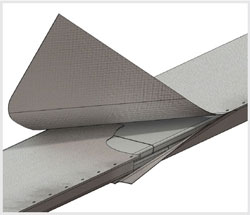
Insulation Pillow installation complete.
6. GASKET — IF REQUIRED
Typically, Fluoroelastomer materials do not require gasket material, while Fluoroplastic materials do.U.S. Bellows offers many unique fabric expansion joint belt designs. When required, gasket material is chosen based on application requirements such as temperature, pressure, ease of installation, etc. The U.S. Bellows drawing will indicate where/when gasket material is required.
Single Ply Fluoroplastic Belt less than 600 degrees F.
Expanded PTFE gasket tape is installed on the frame. Place the gasket on the “cavity” side of the belt attachment bolt hole.
Composite Fluoroplastic Belt Greater than 600 degrees F.
High temperature fiberglass material is used in high temperature applications. Some FLEXXCEL composite belts are shipped with the fiberglass gasket attached to the belt as a cuff. Other FLEXXCEL composite belts are shipped with the fiberglass gasket loose. In high temperature applications, the fiberglass gasket should be installed on the belt attachment flange and under the back up bar.
SHIMS
Where two lengths of back-up-bar come together, place a shim under the back-up-bars, spanning the gap. The gap in back-up-bars should not exceed 1/4″.
7. FABRIC BELT – with factory punched holes
If the fabric belt is shipped with factory punched holes, begin installation of one end of the belt at the top of the duct in the center. Leave this area of the belt unattached, as later this will be where the belt splice is performed. Use clamps to position the belt. Be sure to line up the “corner holes” (if rectangle) first, and then begin installing the back-up-bars and bolts, starting in the corner.
At this point, only hand tighten bolts to assure proper fit up around 2/3 of the joint (If the holes do not align, contact U.S. Bellows for advice — do not drill additional holes or modify existing holes). Install approximately 2/3 of the belt and back-up-bars, leaving an open area available to perform the belt splice. Tighten the bolts snugly.
Perform belt splice. Splice techniques vary — based on the fabric belt construction. Follow U.S. bellows splicing procedures for your specific belt requirements. U.S. Bellows recommends that an ensureAsplice test splice be performed prior to actual splice.
After splice is complete, install remaining back-up-bars. Tighten all bolts to 45 Ft. Lbs.
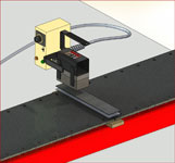
8. FABRIC BELT — without factory punched holes
If the fabric belt is shipped without factory punched holes, begin installation of one end of the belt at the top of the duct in the center.
|
 |
Leave this area of the belt unattached, as later this will be where the belt splice is performed. Use clamps to position the belt and also clamp back-up-bars in place. Using the back-up-bar and frame holes as a guide, drill holes in the belt. At this point, only hand tighten the bolts to assure proper fit up around 2/3 of the joint. Install approximately 2/3 of the belt and back-up-bars, leaving an open area available to perform the belt splice. Tighten bolts snugly.Perform belt splice. Splice techniques vary — based on the fabric belt construction. Follow U.S. Bellows splicing procedures for your specific belt requirements. U.S. Bellows recommends that an ensureAsplice test splice be performed prior to actual splice.
After splice is complete, install remaining back-up-bars. Tighten all bolts to 45 Ft. Lbs.