Introduction to PT&P’s Expansion Joint Course
June 18, 2019
** Turn up your speakers to hear the audio. Please be patient as the screen will become visible
shortly after the speaker begins the presentation. You may click the monitor icon below each
video to view the webinar in full-screen mode.
NOTE: PDH credits are NOT offered for our recorded webinars.
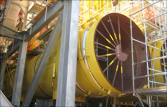
U.S. Bellows provided the total engineering, design, and fabrication package for this project including expansion joints, elbows, duct work, saddle supports, F-type variable spring supports, slide plates, and pipe anchors.
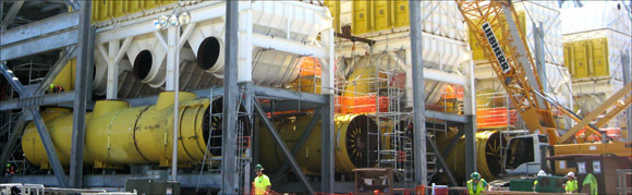
A total of twelve, 119″ dia. double-slotted hinged expansion joints, thirty-six, 72″ dia. elbows, and twelve, 119″ dia., 55″ long header ducts were fabricated for a power plant in Mississippi. The expansion joint assemblies were designed for .5° angular movement, 3/8″ lateral, 1-1/2″ axial compression. The design conditions were 5 psig at 300°F. The duct work was fabricated from A-36 carbon steel material and the bellows were fabricated from 304 stainless steel. A dye penetrant exam, soap and air test, and spot x-ray on all duct seam welds were performed prior to shipping.
Read MoreThe necessary steps for installing all expansion joints shall be pre-planned. The installers shall be made aware of these steps as well as the installation instructions furnished by the manufacturer. The most critical phases of the expansion joint installation are as follows.
Care shall be exercised to prevent any damage to the thin bellows section, such as dents, scores, arc strikes and weld spatter.
No movement of the expansion joint (compression, extension, offset, rotation and especially torsion) due to piping misalignment, for example, shall be imposed which has not been anticipated and designed into the movement capability of the expansion joint. If such movements are imposed, they can result in system malfunction, damage to the bellows or other components in the system. Specifically, cycle life can be substantially reduced, forces imposed on adjacent equipment may exceed their design limits, internal sleeve clearances may be adversely affected, and the pressure capacity and stability of the bellows may be reduced.
Any field pre-positioning shall be performed in accordance with specific instructions which include both the direction and magnitude of the movement.
Anchors, guides and pipe supports shall be installed in strict accordance with the piping system drawings. Any field variances from planned installation may affect proper functioning of the expansion joint and must be brought to the attention of a competent design authority for resolution.
The expansion joint, if provided with internal sleeves, shall be installed with the proper orientation with respect to flow direction.
After the anchors or other fixed points are in place and the piping is properly supported and guided, the expansion joint shipping devices should normally be removed in order to allow the expansion joint to compensate for changes in ambient temperature during the remainder of the construction phase.
Using expansion joints on piping depends upon the configuration of the piping where you will place the expansion joint to absorb thermal expansion or contraction.
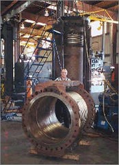
Read MoreThe burst test is primarily conducted on bellows. Normally, hydraulic pressure is slowly increased until failure occurs. Based on the burst test results, a safety factor is applied. This establishes the ultimate pressure rating.

The objective of the burst test is to determine the ultimate pressure resistance. This test is primarily conducted on bellows. Normally, hydraulic pressure is slowly increased until failure occurs. Based on the burst test results, a safety factor is applied. This establishes the ultimate pressure rating.
 |
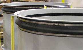 |
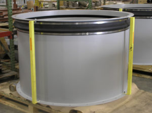
These 59″ x 39.5″ fabric expansion joints were fabricated using a 1/8″ thick neoprene sheet. The joints were then bonded to the carbon steel angles and plates, and secured using stainless steel band clamps, with T-bolt latches. The carbon steel angles and plates were primed and finished at U.S. Bellows, Inc.’s paint production facility. |
Read MoreThe expansion joints were designed to facilitate any vibration and movement during the generator units’ normal operation.

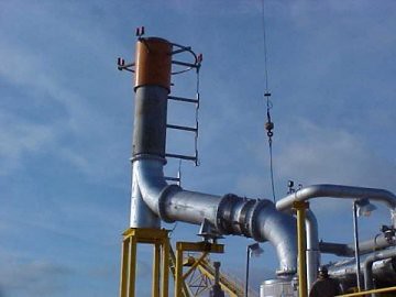
U.S. Bellows, Inc. designed and fabricated this expansion joint exhaust assembly for an oil refinery in Texas. This expansion joint is offset for an offshore platform and weighs approximately 8,000 lbs. It has a design pressure and temperature of 1 PSIG and 1000 degrees, respectively. The air test was conducted to detect any leaks.
Read More
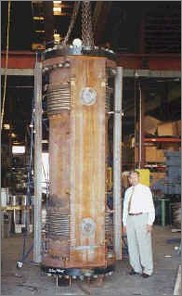

In October 1999, U.S. Bellow, Inc., the expansion joint subsidiary of Piping Technology & Products, Inc., fabricated three expansion joints for an E&C company in Singapore. The expansion joints manufactured included one 36″ single hinged expansion joint, one 36″ double hinged expansion joint and one 36″ double gimbal expansion joint. These expansion joints will be used at a compressor in Singapore. Due to the critical applications of these expansion joints, they were tested per ASME Sect. VIII Div. 1 Appendix 26. The bellows together with the hinge assembly were hydro-tested. Additionally, a dry nitrogen test between the two plies was conducted to ensure that each of the two plies would withstand the design pressure. Gimbal expansion joints allow for restrained angular movement of attached piping in two planes. Expansion joints, in general, allow for axial, lateral, angular and torsional movement in piping systems.
Read MoreTo decrease the thrust force in an axial expansion joint you must decrease the height of the bellows. However, this method will also increase the forces necessary to deflect the bellows.
