Standard Fabric Expansion Joint
High Temperature 3-Layer Expansion Joint
Request a Quote
FEA: Case Studies
Product: Transition Piece
Technical Information: 3D Modeling Software, Parametric Technologies Modeler, Finite Element Analysis Software, COSMOS
Case Study Information
This item was modeled to the specifications included in drawing 6819001-159020. It uses a standard flange at the top as specified. It has been modified to include the extra length of pipe and to eliminate two flanges. The rectangular flange is fabricated of 1.25 x 5 inch stock and is made of A36 steel. The whole transition and pipe is fabricated of 3/8” thick A516 Grade 70 steel and this was expressed in the model. The model has a temperature condition of 105° C/221°F.
Two cases were modeled in which all references to pressure, PSI, refers to PSIG (PSI gage). The first was at operating condition when the transition piece experiences 18.7 PSI internal pressure. The second was at full vacuum when the transition piece experiences 15 PSI external pressure. The stress and displacement results are expressed in the following plots.
*Note: All references to pressure, PSI, refers to PSIG (PSI gage)
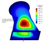
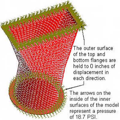
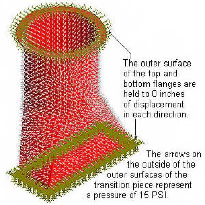
Illustration of Pressures and Displacements – Transition Piece: Internal Pressure = 18.7 PSI
Stress Plot #1 – Transition Piece: Internal Pressure = 18.7 PSI
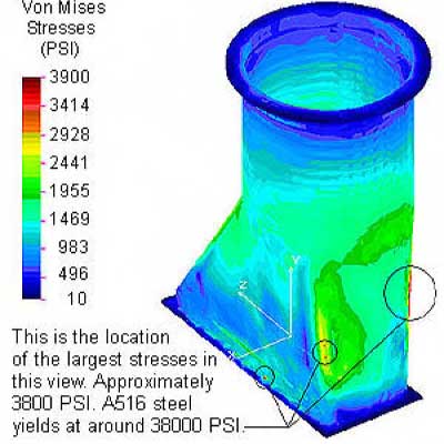
This model has an internal pressure of 18.7 PSI on every internal surface. The chart on the left of the model shows the stresses at every point in the model by a color coding system.
Stress Plot #2 – Transition Piece: Internal Pressure = 18.7 PSI
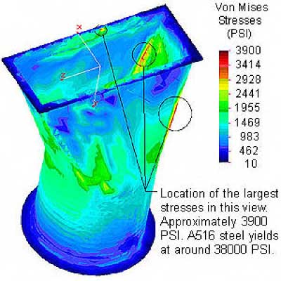
This model has an internal pressure of 18.7 PSI on every internal surface.
Displacement Plot #1 – Transition Piece: Internal Pressure = 18.7 PSI
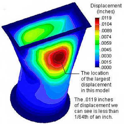
This model has an internal pressure of 18.7 PSI on every internal surface. The chart shows the displacement at every point in the model by a color coding system which represents inches of displacement.
Illustration of Pressures and Displacements – Transition Piece: External Pressure = 15 PSI
Stress Plot #1 – Transition Piece: External Pressure = 15 PSI
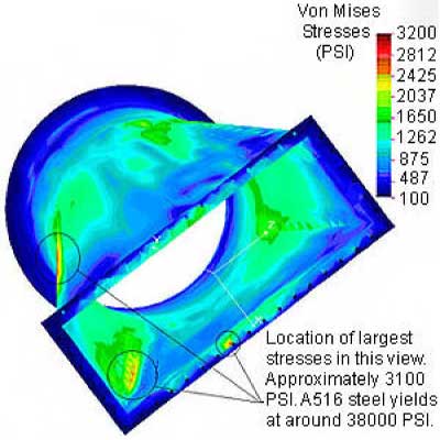
This model has an external pressure of 15 PSI on every external surface. The chart above shows the stresses at every point in the model by a color coding system.
Stress Plot #2 – Transition Piece: External Pressure = 15 PSI
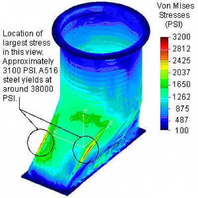
The chart above shows the stresses at every point in the model by a color coding system. This model has an external pressure of 15 PSI on every external surface.
Displacement Plot #1 – Transition Piece: External Pressure = 15 PSI
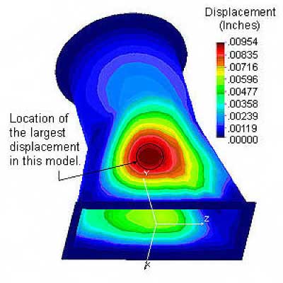
The chart above shows the displacement at every point in the model by a color coding system which represents inches of displacement.
Read MoreObjective
Stress analysis was performed on a dual hinged expansion joint to determine whether the plate thicknesses are sufficient to insure that the stresses are within code allowable.
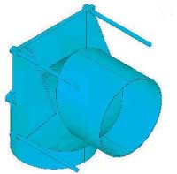
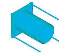
Figures 1 and 2 show a portion of a similar dual hinged expansion joint that was built by U.S. Bellows, Inc. The figures show the connection of the tie rods to the bellows. The tie rods are connected to a plate-gusset assembly, which is welded to the bellows. This note describes a stress analysis to determine whether the plate thicknesses are sufficient to insure that the stresses are within code allowable.
Parameters
| Table 1. Parameters of the two tie rods supports analyzed. | ||
|
Tag
|
EJ-004
|
EJ-009
|
| Bellows Diameter | 36 in | 18 in |
| Plate Dimensions | 46 x 46 x 2 in | 24 3/4 x 24 3/4 x 1 in |
| Tie Rod Diameter | 1 in | 1 in |
| Gusset Thickness | 3/4 in | 3/8 in |
| Load per Tie Rod | 19,297 lbs | 5,443 lbs |
| Steel | A240 tp304H | A240 tp304H |
| Bellows Operating Temp. | 1076 oF | 1076 oF |
| Allowable Stress | 10 ksi | 10 ksi |
Ansys Finite Element Program
The analysis was done using Ansys Finite Element Program. The element used was the Ansys solid 187 element, a 10 node tetrahedral element.
The results for EJ-004 are shown in Figures 3, 4, and 5. Figure 3 shows the stresses in the complete assembly.
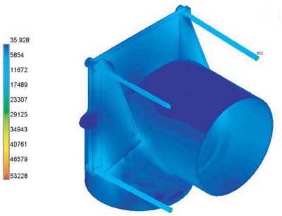
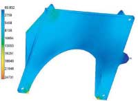
The stresses on the assembly are all nearly below the allowable. There are two small areas where there are stress concentrations, but the areas are small, and the stresses drop rapidly away from the peak. These local areas should not be of concern.
Stresses in EJ-009 Assembly
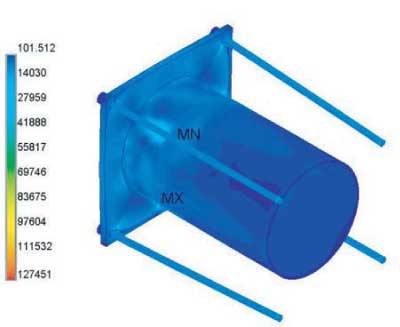
Figure 6 shows the stresses in the complete portion of the assembly analyzed. There are some quite high stresses shown. These are in the pipe at the tip of the guests. They are clearly due to very large change in stiffness at that point, – from 3/8 in. in the pipe to 1 7/8 in. at the tip of the gusset.
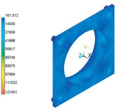
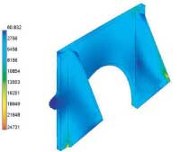
Figure 7 shows the tie rod support plate. The stresses are all clearly below the allowable. In conclusion, the thickness of both plates analyzed are adequate.
Read More